Deploying Radar Flow Velocity Meters for Flash Flood Warning Projects: An Engineering Guide
A practical guide to deploying radar flow velocity meters in flash flood warning projects, covering site selection, installation geometry, joint monitoring, data quality, power, communications, and operations.
Deploying Radar Flow Velocity Meters for Flash Flood Warning Projects: An Engineering Guide
Flash flood warning depends on recognizing change early enough to support a defined response. That is not the same as transmitting a number as quickly as possible. Short-duration intense rainfall, steep catchments, narrow valleys, bridge and culvert constrictions, floating debris, unstable power, and interrupted communications can occur at the same time. In suitable geometry, a radar flow velocity meter can observe water-surface movement without putting a sensing element in the flow. It can add useful field evidence to a warning system, but it does not automatically produce a validated discharge result and it cannot replace rainfall, stage, field observation, or an approved emergency procedure.
A sound deployment starts with the decision that the measurement must support. Is the station intended to indicate strengthening flow, add context near a warning stage, check whether rainfall and channel response are consistent, or supply one input to an independently validated flow estimate? Each purpose changes the required observation area, installation arrangement, sampling interval, quality rules, and manual-check method. This guide describes an engineering framework; device-specific ranges, angles, configuration, and limitations must come from the selected instrument documentation and approved project design.
Define the instrument’s role in the warning chain
A flash flood system may combine rainfall, river stage, surface velocity, camera evidence or field reports, communications status, and platform alerts. The meaning of each signal should be explicit. Otherwise, different measurements can be treated as interchangeable “flood indicators” when they are not.
- Rainfall describes catchment input. It can indicate where and when an intense storm is occurring, but it does not by itself show the discharge at a particular channel section.
- Stage describes water-surface elevation relative to a stated datum. It is central to warning levels and overflow assessment, provided the mounting elevation, zero reference, and checking method are traceable.
- Radar surface velocity describes movement in the approved observation area and averaging window. It can help identify acceleration, backwater effects, culvert influence, or unexpected change. Without cross-section survey, calibration, validation, and continuing review, it is not automatically mean cross-sectional velocity or discharge.
- Instrument-health data include return quality, supply voltage, communications state, and configuration changes. Missing or low-confidence data must be distinguishable from a genuinely calm channel.
At project start, prepare a data-to-action table. For each signal, identify unit, sample and reporting interval, valid-data rule, threshold purpose, notification recipient, verification method, and accountable role. This avoids escalating a transient number as a warning or interpreting an offline station as evidence that the risk has passed.
Select a representative water surface, not merely a convenient mounting point
A mountain stream, gully, or bridge opening can change substantially over a short distance. A survey should consider more than the dry-weather water surface. Use flood marks where available, design water levels, channel-improvement information, bridge and culvert dimensions, bends, tributary junctions, debris paths, and the likely high-flow footprint to determine what water area the instrument will actually observe.
Prefer a location with a reasonably stable flow direction, documented channel form, a target area unlikely to be blocked by members or vegetation, and safe maintenance access. The outside of a sharp bend, a plunge-pool downstream reach, a pier wake, a strong backwater area, a confluence, or a debris-collection point is not necessarily unusable. Its representativeness, however, needs deliberate assessment; a reading obtained during one commissioning visit is not proof of long-term suitability.
Near bridges and culverts, specify whether the target zone is in the approach reach, the upstream ponded area, within the structure, or the downstream outlet. Stage–velocity behavior can differ across those positions and can reverse or become highly local during storms. Keep a station record with directional photographs, plan and cross-section sketches, installation coordinates, target-zone limits, staff-gauge or reference-point location, and obstacles or vegetation that could change the view.
Make installation geometry part of the measurement design
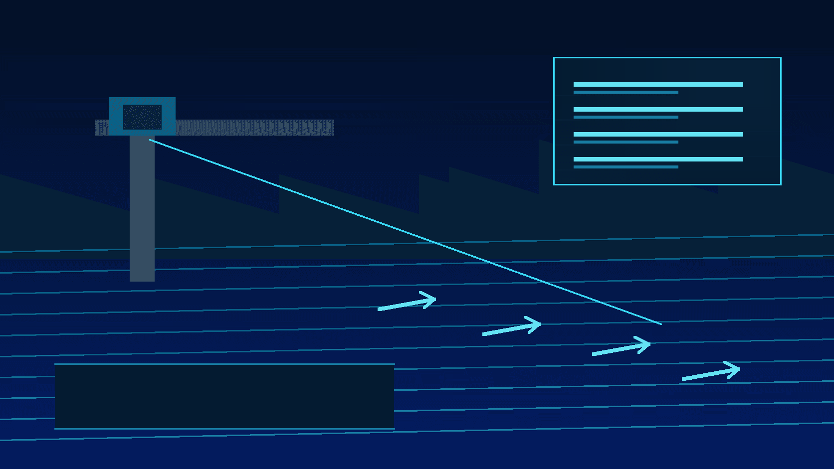
Radar must observe the intended water surface, not simply receive a strong reflection. Confirm mounting height, aiming direction, depression angle, target distance, usable observation window, and relation to the main flow direction using the documentation for the exact device and the approved design. Values recommended for another instrument should not be copied. Brackets, rails, beams, cables, branches, rock faces, and fixed debris can enter the field of view and produce results that remain numerically plausible while no longer representing the intended water area.
After installation, verify aiming and the visible target zone, then retain photographs that show the geometry. Where it can be done safely, observe whether the output trend is reasonable in relation to visible surface movement, rainfall, and stage change across several conditions. That is a plausibility check, not a substitute for discharge validation. If discharge is a required output, qualified personnel need to establish cross-section information, field comparisons, the calculation method, validity limits, and uncertainty treatment.
Maintainability is also a design issue. Prefer arrangements that allow routine inspection without entering water, climbing unnecessarily, or entering a confined space. Where work near a channel, at height, at a bridge, or in a chamber is unavoidable, applicable site procedures for edge protection, confined space, temporary power, and flood-period work still apply. Non-contact sensing can reduce submerged-sensor exposure; it does not remove the duty to manage site hazards.
Use stage, rainfall, and velocity as an interpretable joint observation
One sensor cannot describe every part of a flash flood process. A practical design retains a consistent time basis and presents raw values, quality flags, sample time, receipt time, and platform-ingestion time. Buffered records transmitted after an outage must retain their original sample time and carry a delayed-transmission flag; otherwise a historic observation can be mistaken for a new flood development.
Joint interpretation should follow approved project rules. For example, sustained valid rainfall intensification together with rising stage may raise attention; consecutive quality-qualified surface-velocity changes during rapid stage movement may prompt an operator to review the channel condition; anomalous stage with invalid velocity should prompt a check of the measurement chain and site context. The point is not to add signals mechanically. It is to ensure that each alert conclusion has traceable evidence and a defined verification path.
Separate hydraulic thresholds, rate-of-change thresholds, and equipment-health thresholds. Each rule should state persistence requirements, minimum duration, recovery condition, suppression or deduplication behavior, notification recipient, escalation time, and closure record. Loss of communication, low supply voltage, invalid returns, and configuration changes belong in maintenance workflow, not in a display that implies normal water conditions.
Provide real margin for power and communications
Flash flood stations are often located where coverage is obstructed, power is limited, and reporting is most valuable during severe weather. Test network coverage and antenna location. Evaluate gateway buffering, reconnection behavior, upload protocol, remote diagnostics, and platform intake. For cellular communication, define retry behavior under weak signal, data management, and local retention duration. Alternative links should likewise be tested under rain-related power and communications disturbance rather than assumed reliable from a desk review.
Solar and battery systems should not be sized from ideal peak generation. Base the calculation on real consumption by sensing, transmission, heating or de-fogging, cameras, and supporting equipment, then consider consecutive cloudy days, temperature, aging, shading, and maintenance interval. Grounding, surge protection, sealed cable routes, and lightning protection need to be coordinated with the site design and applicable engineering requirements; they are not optional accessories added after the measurement device is mounted.
Commission for usable evidence and operate through the season
Acceptance should demonstrate that data can support the stated purpose, not merely that an instrument powers up. At the documentation level, verify model, serial number, installation drawing, parameter backup, point list, units, threshold version, and operating material. At the installation level, verify secure mounting, aim, grounding, ingress protection, cable condition, field of view, and safe access. At the communications level, test normal reporting, buffering during interruption, restored transmission, timestamps, remote health, and alarms.
Under conditions that can be checked safely, compare stage with the approved reference method and review whether velocity trends are reasonable in relation to visible flow and known conditions. During a representative observation period, examine completeness, delay, invalid-data frequency, supply condition, communications recovery, and alert closure. Record channel clearing, vegetation removal, bracket adjustments, instrument replacement, firmware updates, channel changes, and parameter modifications in the station record. These changes can alter comparability of the long-term series.
Before the wet season, inspect mounting security, aim and view, solar equipment and cables, grounding and lightning protection, communications quality, clock synchronization, threshold version, contact lists, and manual-check tools. After severe rainfall, inspect debris, sediment, fallen vegetation, scour, structural damage, and data gaps. Connecting those checks to quality flags, alert handling, and site photographs makes later review capable of distinguishing a hydraulic change from a measurement-chain problem.
Conclusion
In flash flood warning, a radar flow velocity meter should be deployed as one element of an interpretable observation chain. Select a representative water-surface target, establish geometry from the specific device requirements, retain stage, rainfall, timing, and quality context, distinguish hydraulic alerts from equipment alerts, and maintain a station record with field verification. When the declared use, engineering conditions, and response process agree, non-contact surface-velocity information can help teams assess developing risk earlier and with more confidence.