Does Slope Displacement Radar Require Reflectors? Target Selection and Deployment Guide
Does slope displacement radar require reflectors? Learn when natural targets may be sufficient, when engineered reflectors can help, and how geometry, reference design, and quality control affect deployment.
Does Slope Displacement Radar Require Reflectors? Target Selection and Deployment Guide
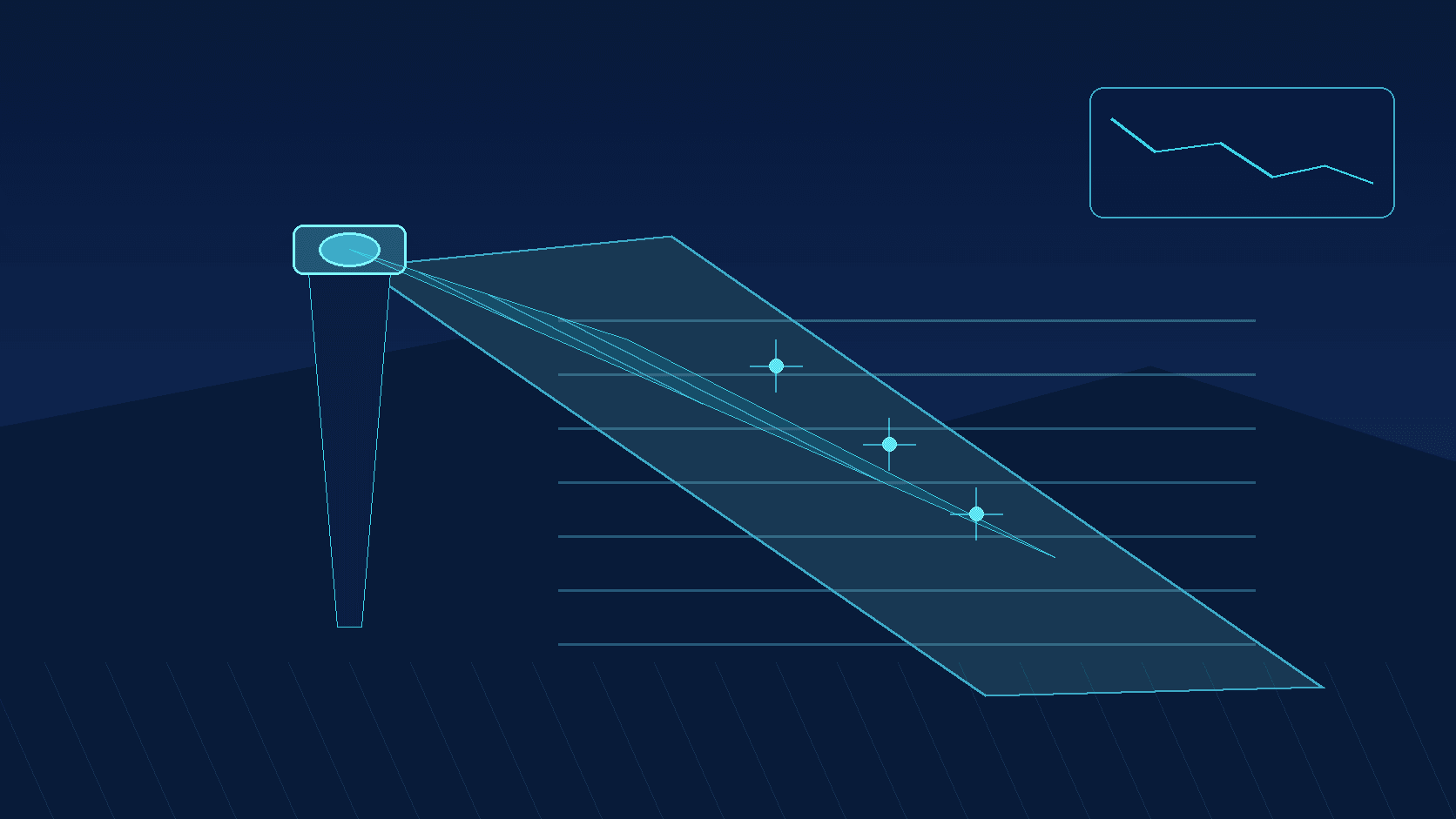
Does slope displacement radar require reflectors? There is no universal yes-or-no answer. A radar can observe change in the relative position of visible areas through returns from natural terrain, rock faces, protection works, or engineered targets. Where a natural target produces a stable, identifiable response and the observation geometry is suitable, a separate reflector may not be necessary. Where natural returns are weak, ambiguous, obscured by vegetation, or inconsistent through changing site activity, a designed reflector or target can improve the ability to identify and revisit a specific location.
A reflector is not a universal accuracy accessory. It changes the target definition and return conditions; it does not replace sound geometry, stable instrument support, data-quality controls, or engineering interpretation. Before deciding whether to install one, a slope monitoring project should define the question it needs to answer. Is the goal to screen a broad visible slope for evolving movement? Or is it to follow a particular rock block, retaining structure, anchor zone, excavation boundary, or crack-adjacent area? The target arrangement should follow that decision.
What Does a Slope Monitoring Radar Measure Directly?
A radar is principally sensitive to movement in the direction between the radar and the target—the line of sight. If a slope’s expected movement direction is not aligned with that line, the observed value represents a component of movement rather than complete three-dimensional displacement. This limitation applies whether the system observes natural terrain or a reflector.
Slope surfaces are also heterogeneous. Bare rock, soil, shotcrete, grid beams, drainage structures, and vegetation can produce different radar responses. Wetting after rainfall, standing water, wind-driven plants, construction equipment, and changing material surfaces can affect target continuity or data interpretation. A site survey and controlled trial are generally more informative than deciding in advance that reflectors are always required or never useful.
| Target approach | Conditions where it may be useful | Potential benefit | Controls still needed | | --- | --- | --- | --- | | Natural terrain or structures | Stable visible rock, soil, or engineered surfaces with repeatable returns | Can support wider-area observation without adding attachments | Check vegetation, occlusion, surface changes, and wet-weather behaviour | | Engineered reflector or target | A defined point is needed, or natural returns are weak or easily confused | Clearer target identity and repeatable location for review | Confirm orientation, mounting stability, weather resistance, and safety | | Combined approach | Both spatial trend screening and key-point review are required | Separates broad-area context from critical-location checks | Align time, coordinate definitions, quality flags, and interpretation rules |
When Should a Project Evaluate Reflectors?
A reflector may be worth evaluating when target identification is the limiting factor. Examples include a soil slope with dense vegetation, a surface that changes seasonally, or a location where returns from adjacent structures overlap. It can also be useful when a project needs a well-defined observation location near a retaining wall, a potentially unstable rock block, an anchor frame, or an excavation edge. A deliberately positioned target can make it easier to relate a radar time series to field inspection points and approved response procedures.
That does not make a reflector an absolute reference. A reflector attached to a moving slope element, a deforming retaining structure, or an unstable support moves with that installation point. It may be an appropriate monitoring target, but it is not automatically a stable reference. If a target is used for verification or alerting, the project should document its location, orientation, fastening condition, expected role, and method of periodic checks. The roles of “observed target” and “stable reference” should be explicitly separated.
Geometry Comes Before Hardware
Observation geometry should be reviewed on drawings and at the actual site. Record the radar-to-slope distance, azimuth, elevation, obstructions, intended target area, and expected direction of movement. If expected sliding is nearly perpendicular to the radar line of sight, the observable component may be small. Installing a stronger target does not remove that geometric limitation.
Where geometry is weak, the project may need a different radar location, another viewpoint, or a complementary instrument. The choice should be made by the approved geotechnical and monitoring design, not by treating a single radar trace as a complete representation of slope behaviour.
Practical Considerations for Reflector Installation
1. Confirm that the natural target is actually inadequate
Start with a site survey or trial observation. Check whether natural targets remain identifiable across representative weather, lighting-independent conditions, vegetation movement, and site operations. A reflector is more defensible when it resolves an observed target-definition problem rather than an assumed one.
2. Design the support as part of the monitoring system
Target orientation, location, and mounting stiffness affect repeatability. Use a weather-resistant arrangement approved for the project, and avoid casually mounting a target on a loose fence, temporary scaffold, vibrating structure, or unassessed part of the slope. High-slope, roadside, and construction locations also require safe access, traffic controls where applicable, and project-specific provisions for power, grounding, and surge protection.
3. Test the installed configuration
Compare observations before and after installation, and record target visibility, signal continuity, and repeatability. Evaluate quality during rainfall, wind, daily temperature changes, and active construction where those conditions are relevant. For alerting applications, establish an early operating baseline and retain flags for missing data, abnormal returns, support disturbance, and device health.
Using Natural Targets and Reflectors Together
Many practical deployments do not require choosing one approach exclusively. Radar may be used to develop a spatial view of change across the visible slope, helping identify areas that merit attention. Carefully selected engineered targets can then support focused time-series review at locations of particular concern. Both sources should be interpreted alongside inspections and other project-approved evidence, which may include rainfall, hydrological conditions, crack observations, GNSS, total-station measurements, or other instruments.
This is particularly important during heavy rain, excavation, unloading, blasting, traffic vibration, or construction-stage transitions. A sudden change in a time series may represent true movement, but it can also result from occlusion, support movement, or a changed processing condition. Alert logic should therefore consider persistence, spatial consistency, device state, weather context, and thresholds approved in the monitoring plan—not one isolated point value.
Field Deployment Checklist
- Define the monitored feature, expected movement direction, and engineering decision the data must support.
- Survey natural target visibility, obstructions, vegetation, and seasonal change; complete a trial observation where feasible.
- If using reflectors, document location, orientation, support stiffness, weather exposure, inspection needs, and installation authorization.
- Separate monitored targets from stable references; do not assume an unverified support is a reference.
- Establish time synchronization, data-quality flags, field records, and an operating baseline.
- Cross-check radar trends with site inspection and other approved monitoring methods.
- Have the responsible project team approve alert thresholds, verification steps, escalation routes, and response ownership.
Frequently Asked Questions
Can slope radar monitor without reflectors?
It can when natural targets remain visible and identifiable, the line-of-sight geometry supports the monitoring objective, and the project has appropriate quality controls. Suitability should be demonstrated through site assessment and trial data, not inferred solely because the radar receives a signal.
Do reflectors automatically improve displacement accuracy?
They may improve target identification and return consistency, but they do not automatically correct line-of-sight projection, radar-support movement, environmental change, or interpretation error. Monitoring performance should be established through the full design, test, and verification process.
Should a reflector be installed in a stable area or on the moving area?
Those placements have different roles. A target on the feature of concern is used to follow that feature. A stable reference must be independently selected and verified as suitable. The monitoring design should state which role each target fulfils.
Conclusion
Whether slope displacement radar requires reflectors depends on target quality, observation geometry, monitoring scale, and the decision the project needs to support. Starting with site reconnaissance and trial observation, then separately designing broad-area trend observation, critical targets, and stable references, provides a stronger foundation than treating a reflector as a default requirement.